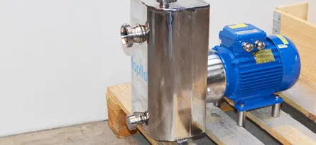





The installation of the CTS Self-Priming Centrifugal Pump requires correct practices to ensure optimal performance.
Tapflo’s CTS range is made up of the CTS-I (industrial) and CTS-H (hygienic) Self-Priming Centrifugal Pumps. The CTS range is manufactured from Stainless Steel with a suction lift up to 4.5m. The series can also be ATEX rated if required. Visit the product pages for more information.
Installation Example
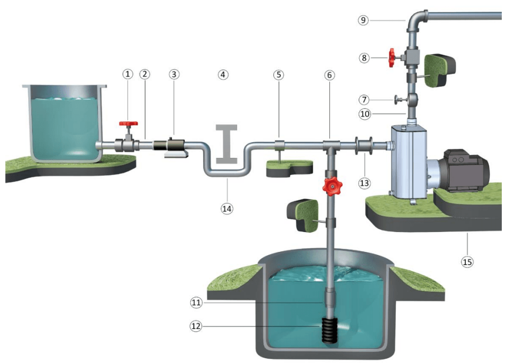
| Number | Permissible | Detail |
| 1 | YES | Gate Valve, may also be fitted closer to the pump in case of long pipework |
| 2 | N/A | With a positive suction head tilt the pipework towards the direction of the pump inlet |
| 3 | YES | In-Line Strainer, required if there are particles present, larger than 6mm |
| 4 | NO | Air Pockets, the circuit needs to be as short and as straight as possible |
| 5 | YES | Pipe Connectors |
| 6 | N/A | Suction line needs to be as short and direct as possible, ideally the same size as the pump inlet or 1 size larger |
| 7 | YES | Attachment for Pressure Gauge or Pressure Relief Valve. It is best practice to install a Pressure Gauge on the discharge of the pump to evaluate where it is working on its curve. A Pressure Relief Valve is required when there is a possibility for “Dead Head” operation or when using a Nozzle for example. |
| 8 | YES | Gate Valve, useful for regulating the performance of the pump |
| 9 | N/A | Bends in the pipework need to be ideally placed after any valves and instrumentation and ideally placed five times the ø of the pipework away. E.g. if the pipework is 25mm, then any bends would ideally need to be placed 125mm away from the pump and any valves or instrumentation |
| 10 | NO | Elbow Joints & other bends on the pump suction or discharge ports |
| 11 | OPTIONAL | Check Valve/Non-return Valve, optional when operating a suction life application |
| 12 | YES | Suction strainer, essential when there is the potential for solids in suspension larger than the capability of the pump. |
| 13 | YES | Expansion joint, indispensable with long pipework and/or hot liquids Anti-Vibration Facility, considered best when using the pump on a fixed & rigid pipework. |
| 14 | YES | Overcome obstacles on both the suction and discharge by lowering the pipework where possible. Essential on the suction side, ideal on the discharge side. This reduces the work the pump has to overcome as well as eliminating the possibility of air pockets. |
| 15 | YES | Fix the pump into the installation by fixing holes provided, the supports and/or based must be level. |