| Model | Max Capacity (m³/hr) | Viscosity Range (cSt) |
|---|---|---|
| YHL 2 | 12 | 10 – 550 |
| YHL 2½ | 38 | 10 – 55,000 |
| YHL 3 | 38 | 10 – 55,000 |
| YHL 4 | 76 | 10 – 55,000 |
| YHL 8 | 250 | 10 – 55,000 |
| YHL 10 | 250 | 10 – 55,000 |
| Model | Max Capacity (m³/hr) | Viscosity Range (cSt) |
|---|---|---|
| YHL 2 | 12 | 10 – 550 |
| YHL 2½ | 38 | 10 – 55,000 |
| YHL 3 | 38 | 10 – 55,000 |
| YHL 4 | 76 | 10 – 55,000 |
| YHL 8 | 250 | 10 – 55,000 |
| YHL 10 | 250 | 10 – 55,000 |

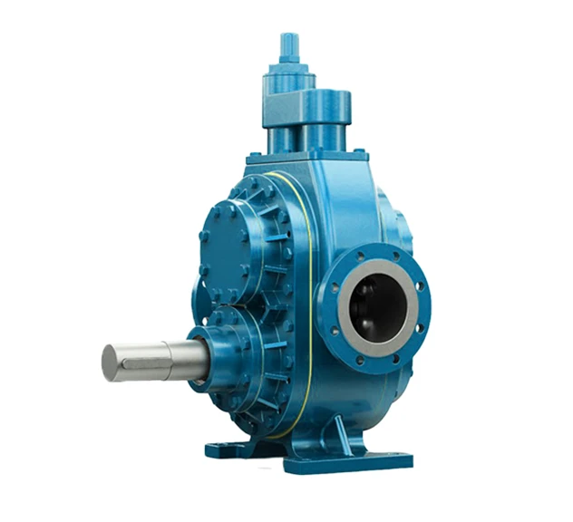
Our Helical External Gear Pump is designed for high-flow, large-transfer applications and versatility in industrial settings. The external gears feature lower operating speeds and helical (angled) teeth in place of straight teeth, for a more gradual operation. Additionally, these pumps are ATEX-approved for use in hazardous environments.
Typical applications for our Helical External Gear Pump:
Download Brochure
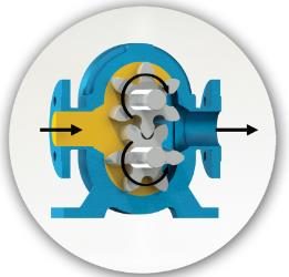
How does a Helical External Gear Pump work?
The pump features a horizontal shaft, 180° port position and has 2 external helical gears with larger angular teeth.
The pump shaft operates, moving the gears that draw liquid into the port. The liquid fills the space between the gears and moves towards the outlet of the pump as the shafts turn.
By-Pass/Pressure Relief Valve Operation:
The intended purpose of a By-Pass or Pressure Relief Valve (PRV) is to ensure that the pump and drive unit are protected from unnecessary damage that may be incurred during over-pressurisation which is mainly caused by closed valve operation or blockages in the discharge line. By-Passes can be either installed on the pipework and route fluid back to the suction of the pump or tank, in the form of a By-Pass Circuit, or indeed installed directly on the pump head, as detailed below.
The By-Pass, when opened, relieves excess fluid and pressure from the discharge section of the pump to the suction side and effectively allow the pump to recirculate within itself until the blockage in the line has been cleared or closed valve opened to allow the process medium to carry on through the system and drop the pressure in the line to an acceptable level for the installed equipment.
As By-Passes are spring-loaded and adjustable, they can be tweaked in situ to cater for changing system or pump requirements.
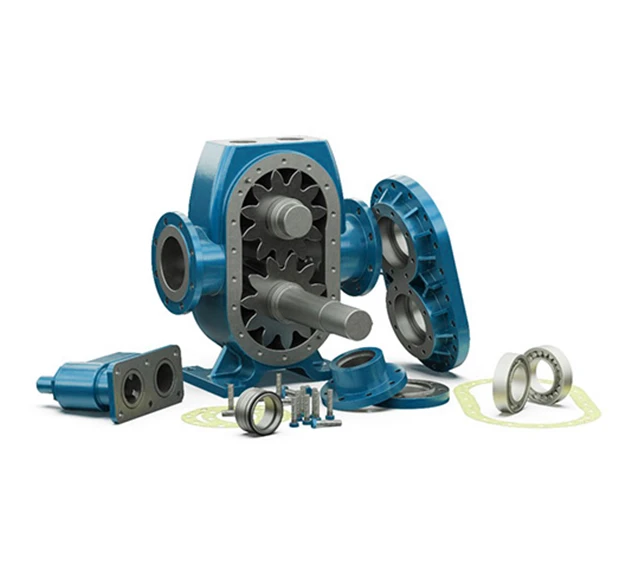
The Helical Gear Pump Range has a compact, robust design with many beneficial features including:
| Max Capacity (m³/hr) | 250m³/hr |
| Max Pressure (m) | 150m |
| Viscosity (cSt) | up to 55,000 cSt |
| Max Speed (rpm) | 1500 rpm |
| Max Temperature (°C) | 350°C |
| Materials & Limits | |
| Connection Sizes | 2” – 10” |
| Capacity Range | 1 – 320 m³/hr |
| Pressure Range | 10 – 150m |
| Temperature Range | up to 350ºC |
| Speed Range | 50 – 1500 rpm |
| Viscosity Range | 20 – 55,000 cSt |
| Pump Body & Cover | Cast Iron, Ductile Cast Iron, Cast Steel, Stainless Steel AISI 304/316 |
| Gears | Cast Iron, Ductile Cast Iron, Cast Steel, Stainless Steel AISI 304/316 |
| Bearings | SnBz12 Bronze, Carbon Graphite, Ina Bushing Bearings |
| Sealing | Soft Seal / Packed Gland, Mechanical Seal |
Sizes Available:
| Model | Max Capacity (m³/hr) | Max Pressure (Bar) | Viscosity Range (cSt) | Max Speed (rpm) | Max Temperature (°C) |
| YHL 2 | 12 | 10 | 10 – 550 | 900 | 200 |
| YHL 2½ | 38 | 15 | 10 – 55000 | 450 | 350 |
| YHL 3 | 38 | 15 | 10 – 55000 | 450 | 350 |
| YHL 4 | 76 | 15 | 10 – 55000 | 450 | 200 |
| YHL 8 | 250 | 15 | 10 – 55000 | 450 | 200 |
| YHL 10 | 250 | 15 | 10 – 55000 | 450 | 200 |