| Model | Max Capacity (m³/hr) | Viscosity Range (cSt) |
|---|---|---|
| YMD ¾ | 1.4 | 10 – 550 |
| YMD 1 | 2.5 | 10 – 550 |
| YMD 1½ | 7.7 | 10 – 550 |
| YMDY 1 | 3 | 10 – 550 |
| YMDY 2 | 7 | 10 – 550 |
| Model | Max Capacity (m³/hr) | Viscosity Range (cSt) |
|---|---|---|
| YMD ¾ | 1.4 | 10 – 550 |
| YMD 1 | 2.5 | 10 – 550 |
| YMD 1½ | 7.7 | 10 – 550 |
| YMDY 1 | 3 | 10 – 550 |
| YMDY 2 | 7 | 10 – 550 |

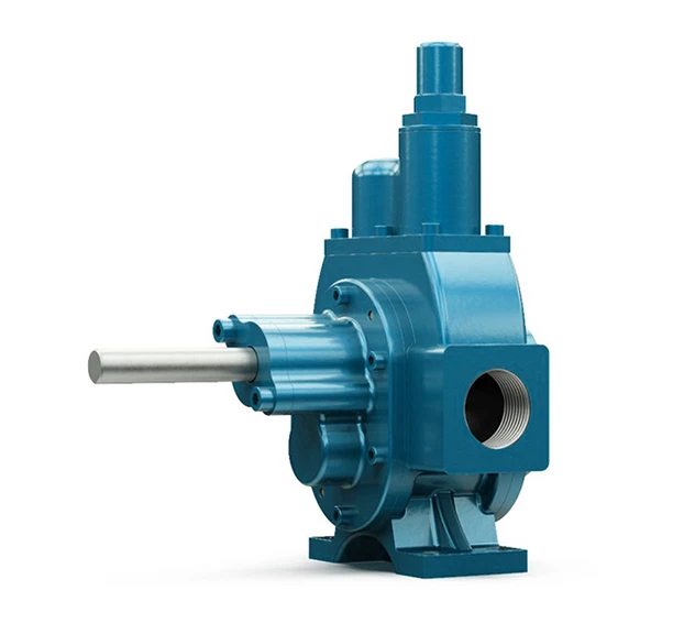
Our Modular External Gear Pump is a robust and efficient pumping solution designed for the Oil, Chemical & Gas industries. This pump consists of two meshing external gears supported on separate shafts with bearings on both sides. They have efficient high-pressure & suction lift capabilities, and pulse-free flows ensure smooth and accurate performance. Additionally, these pumps are ATEX-approved for use in hazardous environments.
Typical applications for our Modular External Gear Pump:
Download Brochure
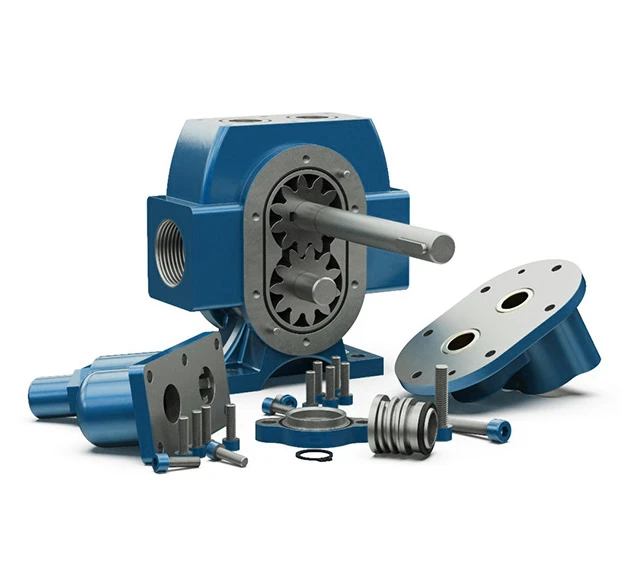
The pump features a horizontal shaft, 180° port position and has 2 external gears.
The pump shaft operates, moving the gears that draw liquid into the port. The liquid fills the space between the gear and is transported towards the pump outlet as the shafts turn.
By-Pass/Pressure Relief Valve Operation:
The intended purpose of a By-Pass or Pressure Relief Valve (PRV) is to ensure that the pump and drive unit are protected from unnecessary damage that may be incurred during over-pressurisation which is mainly caused by closed valve operation or blockages in the discharge line. By-Passes can be either installed on the pipework and route fluid back to the suction of the pump or tank, in the form of a By-Pass Circuit, or indeed installed directly on the pump head, as detailed below.
The By-Pass, when opened, relieves excess fluid and pressure from the discharge section of the pump to the suction side and effectively allow the pump to recirculate within itself until the blockage in the line has been cleared or closed valve opened to allow the process medium to carry on through the system and drop the pressure in the line to an acceptable level for the installed equipment.
As By-Passes are spring-loaded and adjustable, they can be tweaked in situ to cater for changing system or pump requirements.
If you’re looking for a Helical model of this pump, which features larger gears and is ideal for higher volume applications, take a look at our Helical External Gear Pump.
External Gear Pumps come with many benefits, some of which include:
| Max Capacity (m³/hr) | 7,7m³/hr |
| Max Pressure (m) | 300m |
| Viscosity (cSt) | up to 550 cSt |
| Max Speed (rpm) | 1500 rpm |
| Max Temperature (°C) | 100°C |
| Materials & Limits | |
| Connection Sizes | ¾” – 2” |
| Capacity Range | 1 – 7.7 m³/hr |
| Pressure Range | 10 – 300m |
| Temperature Range | up to 100ºC |
| Speed Range | 50 – 1500 rpm |
| Viscosity Range | 20 – 550 cSt |
| Pump Body & Cover | Cast Iron, Cast Steel, Stainless Steel AISI 304/316 |
| Gears | Steel, Stainless Steel AISI 304/316 |
| Bearings | SnBz12 Bronze, Carbon Graphite, Ina Bushing Bearings |
| Sealing | Soft Seal / Packed Gland, Lip Seal, Mechanical Seal |
Sizes Available:
| Model | Max Capacity (m³/hr) | Max Pressure (Bar) | Viscosity Range (cSt) | Max Speed (rpm) | Max Temperature (°C) |
| YMD ¾ | 1.4 | 30 | 10 – 550 | 1500 | 100 |
| YMD 1 | 2.5 | 30 | 10 – 550 | 1500 | 100 |
| YMD 1½ | 7.7 | 30 | 10 – 550 | 1500 | 100 |
| YMDY 1 | 3 | 12 | 10 – 550 | 1500 | 70 |
| YMDY 2 | 7 | 12 | 10 – 550 | 1500 | 70 |