PVDF
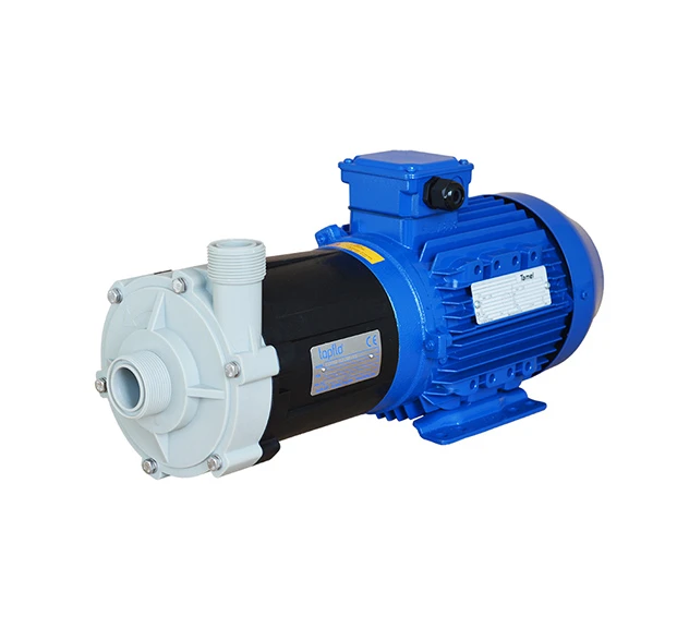
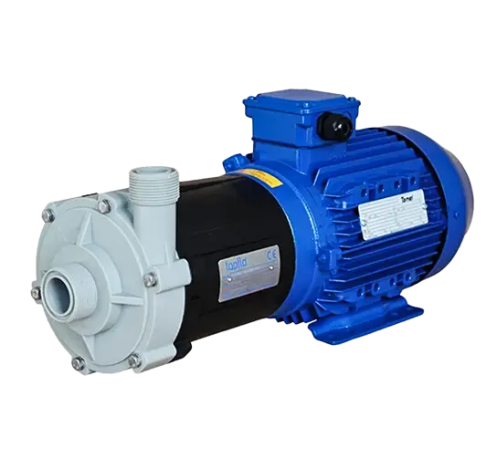
Our CTM Mag Drive Centrifugal Pump is an excellent solution for handling low- to normal-viscosity liquids. The pump’s innovative magnetic seal design ensures leak-free, reliable operation with fewer components, increasing durability.
This Centrifugal Pump is designed with a Magnetically Driven, End-Suction, Close-Coupled, Single-Stage configuration, featuring a Semi-Open or Closed Impeller. This pump offers superior mechanical strength and excellent corrosion resistance for various industrial applications.
Typical applications include:
| Specification | Data |
|---|---|
| Capacity | 28m3/h |
| Max Discahrge Pressure | 6 bar |
| Temperature Ranges (ºC) | PP Pumps: 0-70ºC PVDF Pumps: 0-80ºC (CTM 20) / 0-90ºC (CTM25 – 50) |
| Viscosity Max (cPs) | 200 |
| Casing & Isolation Shell Material | PP-GF (30%) or PVDF |
| Impeller Material | PP or PVDF |
| Motor | IEC standard, 3×400 VAC (other on request), 2900 rpm, IP55, B34 frame, IE3 |
How Mag Drive Pumps Work
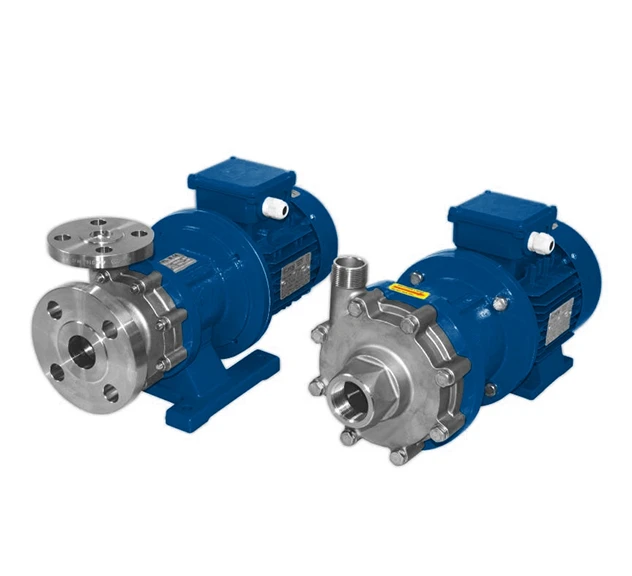
Mag Drive Centrifugal Pumps use a magnetic coupling rather than a direct mechanical shaft to transfer power from the motor to the impeller. This seal-less design eliminates the risk of leakage, making them ideal for handling hazardous or corrosive fluids in industries.
These close-coupled, single-stage centrifugal pumps are available with semi-open or closed impellers and are manufactured from reinforced PP or PVDF for excellent corrosion resistance and durability.
The pump must be primed and supplied with adequate Net Positive Suction Head (NPSH). During operation, liquid enters the impeller eye, where centrifugal force accelerates it through the casing and into the discharge line, creating a continuous pumping cycle.
Torque is transmitted via a magnetic coupling between the motor and impeller. If the impeller becomes blocked or excessive torque occurs, the magnets automatically decouple to protect the motor from damage, then re-engage once normal conditions are restored.
Magnet Cage System
The magnets are totally encapsulated in their cage with a unique system that avoids the use of resins and glue. This grants a safe system with better performance at high temperatures. Furthermore, the impeller is injection moulded, resulting in excellent performance and no weak points.