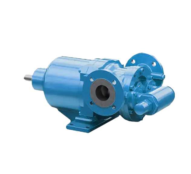
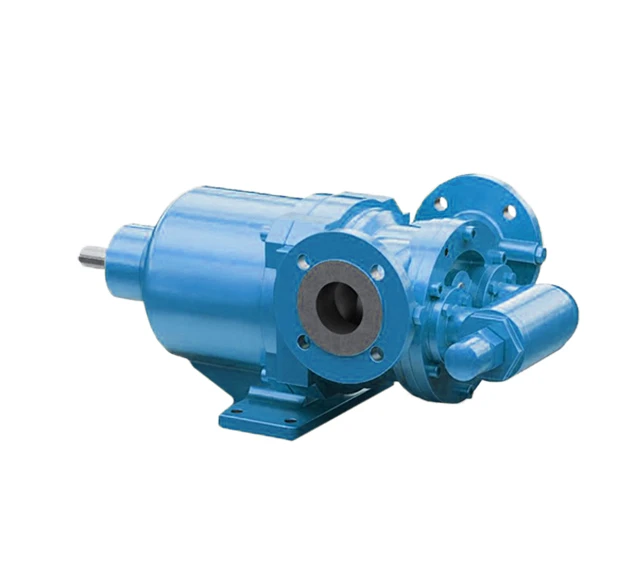
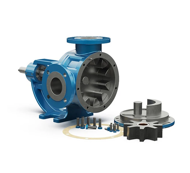
lead forensics image

Magnetically Driven Internal Eccentric Gear Pumps

Magnetically Driven Internal Eccentric Gear Pump

Magnetically Driven Internal Eccentric Gear Pumps

ATEX icon ISO icon CE icon EN10204 icon

The Magnetically Driven Internal Eccentric Gear Pump is a reliable and efficient solution based on the simple “gear within gear” principle. The rotary and idler gears in the pump head create cavities between their teeth, achieving positive displacement. During each revolution, a fixed volume of fluid enters the casing through the suction port, filling the spaces between the gear teeth. The crescent within the pump head then separates the fluid as the idler gear turns on the pump shaft. The Internal Eccentric Gear Pump delivers smooth and accurate pumping which makes it an excellent choice for various applications.

  • Only 2 moving components within the process medium
  • Capable of pumping fluids too viscous for a Centrifugal Pump
  • Efficient suction lift applications
  • Bi-directional pumping action
  • ATEX-rating available for use in hazardous environments

Max. Flow:

Max. Head:

Max. Temp:

Material:

55m³/hr

120m

250°C

Metal

ATEX icon ISO icon CE icon EN10204 icon

How does an Internal Eccentric Gear Pump work?

Operating Principle of Yildez Eccentric Gear Pump

Image 1: Fluid entering the pump: The orange coloured section in the image represents the process medium as it is entering the pump suction port, pump casing & filling the cavities between the Idler Gear (Red) & Rotary Gear (Brown). The 3 arrows indicate the direction of fluid passage through the pump and rotational direction of the gears.

Image 2: Fluid filling the cavities & split of flow: As the fluid progresses through the pump head and fills the cavities between the gears it is also separated by the crescent shape in the pump head, which acts as a seal preventing back flow between the suction & discharge ports.

Image 3: Pump almost flooded: As the fluid fully fills the casing all cavities between the gears are completely filled in the form of locked pockets of fluid to guarantee absolute volume control and enable the pump to deliver a fixed volume per revolution.

Image 4: Pump is flooded & starts to discharge the process medium under pressure: Once the pump is fully flooded, the rotor and idler gears mesh together and form a liquid seal which is equidistant between the pump ports which then enables the fluid to exit the discharge of the pump under pressure. The delivery pressure is dependent on the installed power of the motor.

The Magnetically Driven Internal Eccentric Gear Pumps are ideal for the following:

  • Caustic, isocyanate, adhesive, solvents
  • Paint/dye industry
  • Pharmaceutical Industry
  • Detergent
  • Food Industry

Max Flow: 55m³/hr
Max Pressure: 120 meters
Viscosity Range: 10 – 5,500 cSt
Max Speed: 1400 rpm
Max Temp: 250ºC

Materials and Limits

Connection Sizes: 1½” – 2½”

Capacity Range: 0.1 – 55 m³/hr

Pressure Range: 10 – 120 meters

Temperature Range: up to 250ºC

Speed Range: 20 – 1500 rpm

Viscosity Range: 20 – 5000 cPs

Pump Body & Cover: 

Cast Iron

Spheroidal Cast Iron

Cast Steel

Stainless Steel AISI 304/316

Gears: 

Spheroidal Cast Iron

Cast Steel

Stainless Steel AISI 304/316

CrNi Stainless Steel

Bearings: 

SnBz12 Bronze

Carbon Graphite

Silicon Carbide

Hard Metal Coated Steel

Sealing: Sealless Mag-Drive

Largest UK Stock

Same Day Quote

Fastest Delivery

Largest UK Stock

Same Day Quote

Fastest Delivery

Looking for more information about the services offered by Tapflo UK?

Our friendly team at Tapflo UK would be more than happy to assist you further with any pump solutions, delivery information or questions you have. If you need additional support on-site, you can speak to a member of the team today to organise a site visit.

Give us a call now:

02380 252 325

Generic selectors
Exact matches only
Search in title
Search in content
Post Type Selectors
knowledgebase
careers
catalogue
Filter by Categories
Blog
Case Studies