| Model | Connections | Motor Power kW |
|---|---|---|
| CTM 20-7 | 3/4" / 3/4" | 0.12 |
| CTM 25-8 | 1" / 1" | 0.25 |
| CTM 25-10 | 1" / 1" | 0.55 - 0.75 |
| CTM 32-12.5 | 1 1/4" / 1" | 0.75 - 1.1 |
| CTM 40-12.5 | 1 1/2" / 1 1/4" | 1.5 - 2.2 |
| CTM 50-12.5 | 2" / 1 1/2" | 3-4 |
| Model | Connections | Motor Power kW |
|---|---|---|
| CTM 20-7 | 3/4" / 3/4" | 0.12 |
| CTM 25-8 | 1" / 1" | 0.25 |
| CTM 25-10 | 1" / 1" | 0.55 - 0.75 |
| CTM 32-12.5 | 1 1/4" / 1" | 0.75 - 1.1 |
| CTM 40-12.5 | 1 1/2" / 1 1/4" | 1.5 - 2.2 |
| CTM 50-12.5 | 2" / 1 1/2" | 3-4 |
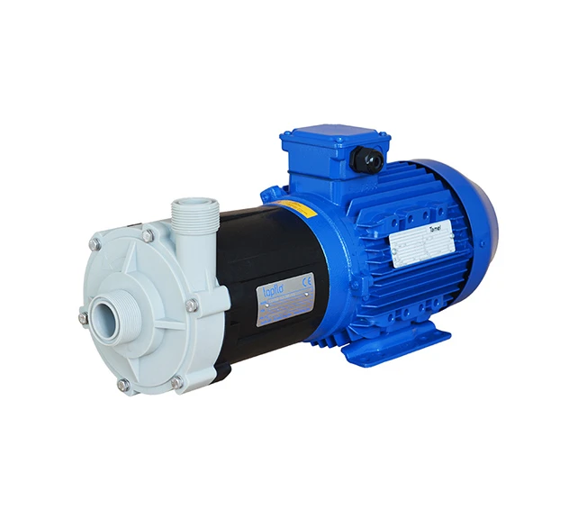
Our CTM Mag Drive Centrifugal Pump is an excellent solution for handling low to normal viscosity liquids.
The pump’s innovative magnetic seal design ensures leak-free and reliable operation with fewer components for increased durability. This Centrifugal Pump is designed with a Magnetically Driven, End-Suction, Close-Coupled, Single-Stage configuration, featuring a Semi-Open or Closed Impeller.
The materials used in their construction are Glass Fibre Reinforced Polypropylene or PVDF, offering superior mechanical strength and excellent corrosion resistance for various industrial applications. For enhanced operational versatility, this pump is available as part of the CTM-IBC portable system.
Typical applications for our Mag Drive Centrifugal Pump:
Download Brochure
Download Manual
Varying from the standard pumping mechanism, Mag Drive Centrifugal Pumps are designed to connect the motor to the pump by magnets instead of a direct mechanical shaft. The drive magnet works the pump, ‘driving’ the pump rotor, which is magnetically coupled to the primary shaft driven by the motor. Magnetic Pumps are used in industries where leakage of the agent being pumped could cause damage, such as in the chemical or nuclear industries.
The Centrifugal Pumps are Magnetically Driven End Suction, Close Coupled; Single Stage Centrifugal Pumps feature a Semi-Open or Closed Impeller. They are manufactured from either Glass Fibre Reinforced Polypropylene or PVDF to offer high mechanical and corrosion resistance for a plethora of applications at competitive pricing.
How does a Mag Drive work?
In order to start the pump, the casing must be filled with liquid before start-up and have a positive suction head to operate efficiently. The NPSHr (Net Positive Suction Head Required) can be provided during the selection and assessment of the pump for your intended application.
Upon start-up, the liquid enters the pump casing axially onto the eye of the impeller. The rotating impeller generates a centrifugal force accelerating the liquid through the pump casing and into the discharge piping. As the fluid is accelerated by the impeller and thrown towards the discharge outlet, a low-pressure point is generated at the eye of the impeller, effectively drawing fluid from the suction side to the pump and continuing the pumping cycle.
Unlike standard close-coupled centrifugal pumps where the impeller is connected to the motor shaft directly, in a CTM Magnetically Driven Centrifugal Pump, the torque from the motor shaft is transmitted to the impeller by means of a magnetic coupling. The drive magnet is fixed on the motor shaft. The magnets installed in the drive magnet and in the impeller/magnet assemblies have different polarities.
When the pump is at rest, the magnets of both parts are aligned. When the motor is started, and the drive magnet starts to rotate, the magnets create an attraction and repulsion force, thus forcing the impeller to rotate. If the impeller gets blocked or the pumped liquid is too dense and too much torque will be generated on the motor shaft, the magnet will de-couple, and no damage will be done to the motor. When the pump comes to a stop, the magnets will re-couple. Between both magnet assemblies, there is an isolation shell that separates the liquid side from the motor side and from entering the atmosphere.
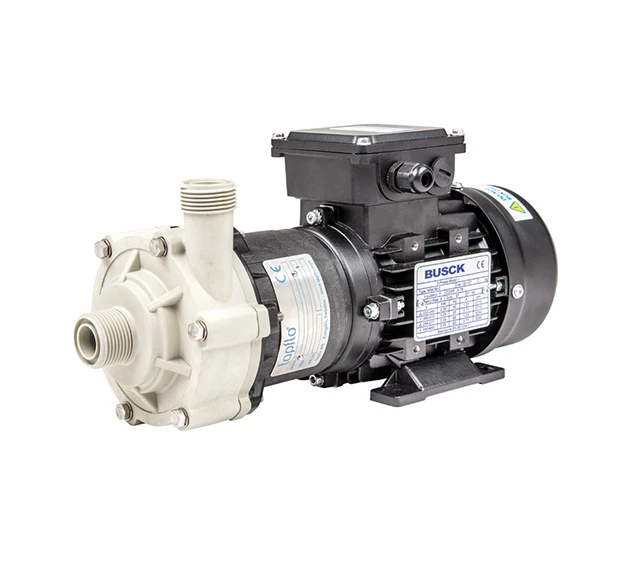
The CTM Mag Drive Centrifugal Pump is a close-coupled compact pump ideal for service in confined or restricted spaces like in OEM installations. Benefits include:
The wetted components are non-metallic injection moulded thermoplastics enabling excellent corrosion resistance.
Magnet Cage System
The magnets are totally encapsulated in their cage with a unique system that avoids the use of resins and glue. This grants a safe system with better performance at high temperatures. Furthermore, the impeller is injection moulded, resulting in excellent performance and no weak points.
This pump is also available as part of our CTM-IBC portable system.
| Casing & Isolation Shell | PP-GF (30%) or PVDF |
| Impeller | PP or PVDF |
| Lantern (Not Wetted) | PP-GF (30%) |
| Static Bushings | Ceramic (Std.) or SiC |
| Rotating Bushings | PTFE-Graphite (Std.) or SiC |
| O-Rings | FKM, EPDM, FFKM, FEP / Silicon |
| Magnets | NdFeB |
| Motor | IEC standard, 3×400 VAC (other on request), 2900 rpm, IP55, B34 frame, IE3 |
| Pressure Ratings | CTM20: PP pumps: PN4 at 20°C, PN2 at 70°C PVDF pumps: PN4 at 20°C, PN2 at 80°C
CTM25, CTM32, CTM40 and CTM50: PP pumps: PN6 at 20°C; PN2 at 70°C PVDF pumps: PN6 at 20°C; PN2 at 90°C |
| Temperature Ranges | PP Pumps: 0-70ºC PVDF Pumps: 0-80ºC (CTM 20) / 0-90ºC (CTM25 – 50) |
| Viscosity | 200 cPs (max) |
Dimensions:
Dimensions are in mm and based on standard build constructions. DWG & STEP Files are available upon request for integration into system build designs.
| Model | CTM 20-7 | CTM 25-8 | CTM 25-10 | CTM 32-12.5 | CTM 40-12.5 | CTM 50-12.5 | ||||
| A | 70 | 90 | 100 | 105 | 105 | 110 | ||||
| B | 48 | 58.5 | 63 | 56 | 56.5 | 54 | ||||
| C | 93.5 | 100.5 | 136.5 | 164 | 165 | 189 | ||||
| ØE | 15 | 18 | 18 | 15 | 23 | 30.8 | ||||
| øF | 15 | 18 | 18 | 23 | 30.5 | 42 | ||||
| G | ¾” | 1” | 1” | 1¼” | 1½” | 2” | ||||
| H | ¾” | 1” | 1” | 1” | 1¼” | 1½” | ||||
| L | 248.5 | 279 | 334.5 | 374.5 | 402.5 | 446 | 453 | |||
| M | 36 | 40 | 45 | 54.5 | 56 | 63 | 70 | |||
| N* | 71 | 80 | 80 | 100 | 125 | 140 | ||||
| P* | 9 | 10 | 10 | 13 | 14 | 15 | ||||
| Q | 56 | 63 | 71 | 80 | 90 | 100 | 112 | |||
| R | 35 | 39.5 | 43.5 | 58.5 | 58.5 | 52 | ||||
| S* | 90 | 100 | 112 | 125 | 140 | 160 | 190 | |||
| T | 112 | 126 | 141 | 160 | 170 | 200 | 230 | |||
| U* | 5.5 | 7 | 7 | 10 | 10 | 12 | ||||
| Motor Specifications | ||||||||||
| Power, kW | 0.12 | 0.25 | 0.55 | 0.75 | 0.75 | 1.1 | 1.5 | 2.2 | 3.0 | 4.0 |
| Frame Size | 56 | 63 | 71 | 80 | 90 | 100 | 112 | |||
| Weight, Kg (PP) | 4.3 | 5.7 | 8.75 | 9 | 11.7 | 15.7 | 24 | 25.5 | 31.55 | – |
| Weight, Kg (PVDF) | 4.45 | 5.9 | 9.2 | 9.4 | 12.2 | 16.2 | 24.65 | 26.2 | 32.15 | – |
| Optional Connections | ||||||||||
| Flanged | – | DN25 | DN25 | DN32 / DN25 | DN40 / DN32 | DN50 / DN40 | ||||
| Hose Tails | – | Ø25 | Ø25 | Ø32 / 25 | Ø40 / 32 | Ø50 / 40 | ||||