| Model | Max Capacity (m³/hr) | Viscosity Range (cSt) |
|---|---|---|
| YMG 1½ | 5.7 | 10 - 5,500 |
| YMGF 2 | 15 | 10 - 5,500 |
| YMGF 2½ | 25.5 | 10 - 5,500 |
| YMGUF 2½ | 32 | 10 - 5,500 |
| YMGF 3 | 32 | 10 - 5,500 |
| YMGBF 3 | 55 | 10 - 5,500 |
| Model | Max Capacity (m³/hr) | Viscosity Range (cSt) |
|---|---|---|
| YMG 1½ | 5.7 | 10 - 5,500 |
| YMGF 2 | 15 | 10 - 5,500 |
| YMGF 2½ | 25.5 | 10 - 5,500 |
| YMGUF 2½ | 32 | 10 - 5,500 |
| YMGF 3 | 32 | 10 - 5,500 |
| YMGBF 3 | 55 | 10 - 5,500 |

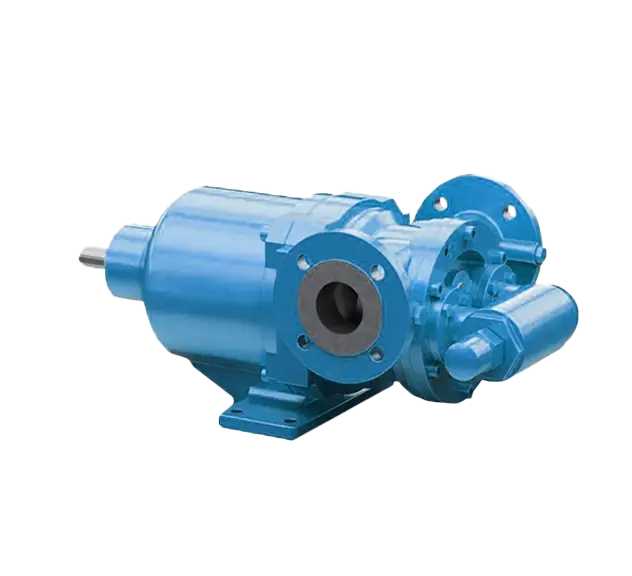
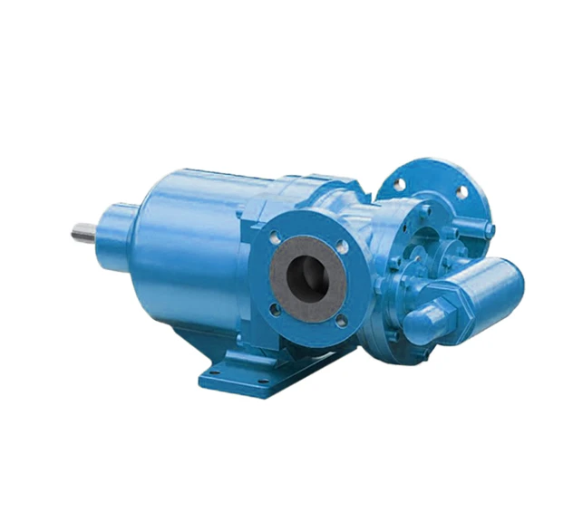
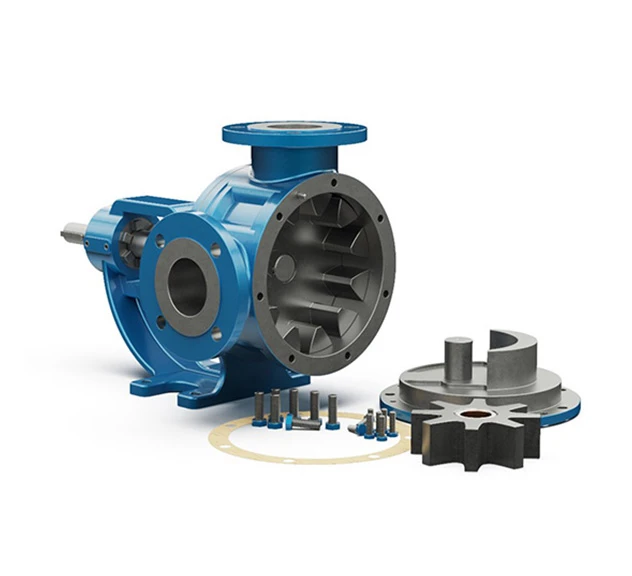
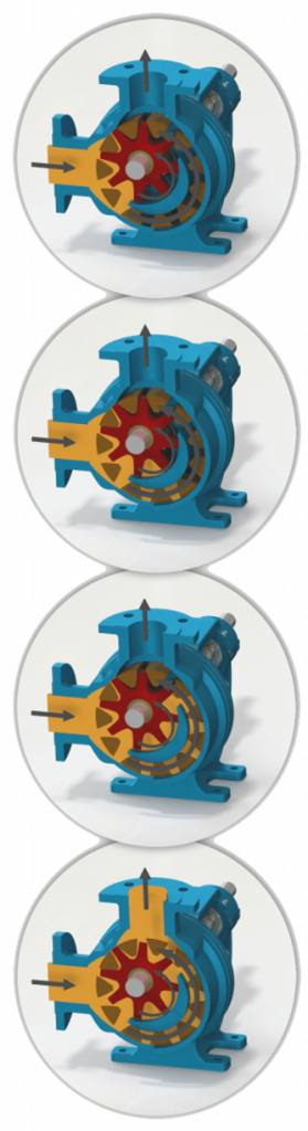
Tapflo's Mag Drive (Magnetically Driven) Internal Eccentric Gear Pump is a reliable and efficient solution based on the simple “gear within gear” principle. Capable of pumping liquids that are too viscous for a standard Centrifugal Pump, these pumps deliver efficient suction lift and bi-directional operation, ensuring optimal efficiency and versatility. Additionally, this pump uses magnetic coupling and sealed pump housing, eliminating the need for mechanical seals, making it ideal for corrosive or hazardous environments.
Typical applications for our Magnetically Driven Internal Eccentric Gear Pump:
Download Brochure
Gear Pumps are classified as Rotary Positive Displacement Pumps and are well-suited for the transfer of viscous and semi-viscous fluids for a range of applications and industries.
Gear Pumps are classified as Rotary Positive Displacement Pumps and are well-suited for the transfer of viscous and semi-viscous fluids for a range of applications and industries.
The Mag Drive Internal Eccentric Gear Pump has many benefits, some of which include:
If you’re looking for a modular model of the Mag Drive Gear Pump that features 2 smaller gears and is suitable for low-volume, high-pressure applications, take a look at our Mag Drive Modular Gear Pump.
| Max Capacity (m³/hr) | 55m³/hr |
| Max Pressure (m) | 120m |
| Viscosity (cSt) | up to 5,500 cSt |
| Max Speed (rpm) | 1400 rpm |
| Max Temperature (°C) | 250°C |
| Materials & Limits | |
| Connection Sizes | 1½” – 2½” |
| Capacity Range | 0.1 – 55 m³/hr |
| Pressure Range | 10 – 120m |
| Temperature Range | up to 250ºC |
| Speed Range | 20 – 1500 rpm |
| Viscosity Range | 10 – 5,500 cSt |
| Pump Body & Cover | Cast Iron, Spheroidal Cast Iron, Cast Steel, Stainless Steel AISI 304/316 |
| Gears | Spheroidal Cast Iron, Cast Steel, Stainless Steel AISI 304/316, CrNi Stainless Steel |
| Bearings | SnBz12 Bronze, Carbon Graphite, Silicon Carbide, Hard Metal Coated Steel |
| Sealing | Sealless Mag-Drive |
Sizes Available:
| Model | Max Flow (m³/hr) | Max Pressure (Bar) | Viscosity Range (cSt) | Max Speed (rpm) | Max Temperature (°C) |
| YMG 1½ | 5.7 | 12 | 10 – 5,500 | 1400 | 250 |
| YMGF 2 | 15 | 12 | 10 – 5,500 | 500 | 250 |
| YMGF 2½ | 25.5 | 12 | 10 – 5,500 | 500 | 250 |
| YMGUF 2½ | 32 | 12 | 10 – 5,500 | 500 | 250 |
| YMGF 3 | 32 | 12 | 10 – 5,500 | 500 | 250 |
| YMGBF 3 | 55 | 12 | 10 – 5,500 | 500 | 150 |