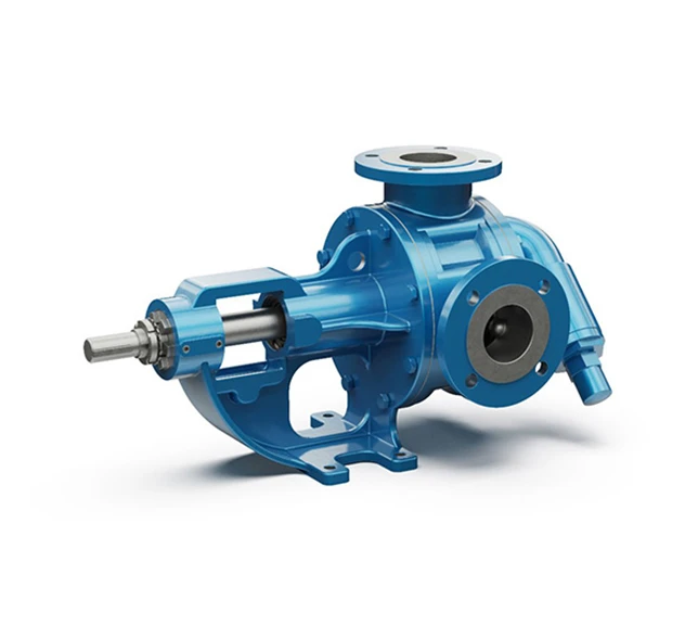
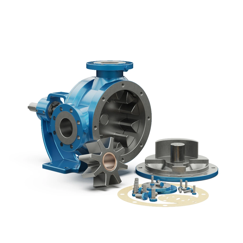
Our Internal Eccentric Gear Pump is a reliable and efficient solution based on the simple “gear within gear” principle. It features a large internal gear with internal teeth and a smaller gear (pinion), separated by a fixed crescent to achieve positive displacement. This ATEX-available pump is capable of pumping viscous fluids with exceptional performance at low speeds, low pulsation and a smooth flow for consistent product quality.
Typical applications for our Internal Eccentric Gear Pump:
Download Brochure
The “gear within gear” principle means that there are only two moving components within the process medium. The positive displacement is achieved by filling the cavities between the teeth of both the rotary and idler gears located in the pump head with the desired fluid.
With each revolution, a fixed volume of fluid enters the casing through the suction port, filling the space between the teeth of the gears. The crescent within the pump head then separates the fluid as the idler gear turns on the pump shaft
Fluid entering the pump
As the process medium enters the pump suction port and casing, it fills the cavities between the Idler Gear and Rotary Gear. Fluid is transported through the pump in the rotational direction of the gears.
Fluid filling the cavities & split of flow
As the fluid progresses through the pump head and fills the cavities between the gears, the fixed crescent splits the fluid and additionally acts as a seal, preventing backflow between the suction & discharge ports.
Flooding of the pump
As the fluid fills the casing, all cavities between the gears are filled, forming locked pockets of fluid to guarantee absolute volume control and enable the pump to deliver a fixed volume per revolution.
The pump is flooded & starts to discharge the process medium under pressure
Once the pump is fully flooded, the rotor and idler gears mesh together and form a liquid seal which is equidistant between the pump ports, which then enables the fluid to exit the discharge of the pump under pressure. The delivery pressure is dependent on the installed power of the motor.

The External Gear Pump range features many benefits, some of which include:
| Max Capacity (m³/hr) | 200m³/hr |
| Max Pressure (Bar) | 15 Bar |
| Viscosity (cSt) | up to 55,000 cSt |
| Max Speed (rpm) | 1400 rpm |
| Max Temperature (°C) | 200°C |
| Materials & Limits | |
| Connection Sizes | 3/8″ – 8″ |
| Capacity Range | 0.1 – 250m³/hr |
| Pressure Range | 1 – 15 Bar |
| Temperature Range | up to 200ºC |
| Speed Range | 20 – 1720 rpm |
| Viscosity Range | 20 – 5,500 cSt |
| Pump Body & Cover | Cast Iron, Spheroidal Cast Iron, Cast Steel, Stainless Steel AISI 304/316 |
| Gears | Spheroidal Cast Iron, Cast Steel, Stainless Steel AISI 304/316, CrNi Stainless Steel |
| Bearings | SnBz12 Bronze, Carbon Graphite, Silicon Carbide, Hard Metal Coated Steel |
| Sealing | Soft Seal / Packed Gland, Rotatherm Seal, Lip Seal, Mechanical Seal, Cartridge Type Mechanical Seal |
Sizes Available:
| Model | Max Capacity (m³/hr) | Max Pressure (Bar) |
Viscosity Range (cSt) | Max Speed (rpm) | Max temperature (°C) |
| Bareshaft units with In-Line Connections for Low Flow & Low Viscosity Fluids & High Pressures | |||||
| YMK ¾ | 0,4 | 15 | 10 – 1650 | 1400 | 100 |
| YMK ½ | 0.8 | 15 | 10 – 1650 | 1400 | 100 |
| YMK 1 | 2 | 10 | 10 – 1650 | 1400 | 120 |
| YMK 1½ | 5.7 | 12 | 10 – 1650 | 1400 | 200 |
| YMKU 1½ | 6.7 | 12 | 10 – 1650 | 1400 | 200 |
| YMK 2 | 9 | 12 | 10 – 1650 | 1400 | 200 |
| Bareshaft Units with 90º Connections for Higher Viscosity Fluids & Medium Pressures | |||||
| YP 1 | 3 | 7 | 10 – 55000 | 1400 | 100 |
| YP 1½ | 5.5 | 7 | 10 – 55000 | 1400 | 100 |
| Heavy Duty Bareshaft Units for Higher Viscosity Fluids, Flows & Pressures | |||||
| YK 1 | 3 | 14 | 10 – 55000 | 1400 | 200 |
| YK 1½ | 6 | 14 | 10 – 55000 | 1400 | 200 |
| YKU 1½ | 7 | 14 | 10 – 55000 | 1400 | 200 |
| YKF 20 0 | 15 | 14 | 10 – 55000 | 900 | 200 |
| YKKF 2 | 11.6 | 14 | 10 – 55000 | 500 | 200 |
| YKF 2 | 15 | 14 | 10 – 55000 | 500 | 200 |
| YKF 2½ | 25.5 | 14 | 10 – 55000 | 500 | 200 |
| YKUF 2½ | 32 | 14 | 10 – 55000 | 420 | 200 |
| YKF 3 | 32 | 14 | 10 – 55000 | 420 | 200 |
| YKBF 3 | 55 | 14 | 10 – 55000 | 400 | 200 |
| YKF 4 | 55 | 14 | 10 – 55000 | 400 | 200 |
| YKYF 40 0 | 90 | 14 | 10 – 55000 | 400 | 200 |
| YKBF 4 | 120 | 14 | 10 – 55000 | 400 | 200 |
| YKF 5 | 110 | 9 | 10 – 55000 | 280 | 200 |
| YKF 6 | 135 | 9 | 10 – 55000 | 350 | 200 |
| YKF 8 | 200 | 9 | 10 – 55000 | 220 | 200 |
| Close Coupled Units for Low to Medium Viscosity Fluids & Pressures | |||||
| YMB 1 | 3 | 10 | 10 – 1650 | 1400 | 70 |
| YMB 1½ | 5.7 | 10 | 10 – 1650 | 1400 | 70 |
| YMBF 2 | 15 | 5 | 10 – 5500 | 500 | 70 |
| YMBF 2½ | 23 | 5 | 10 – 5500 | 450 | 70 |
| YMBUF 2½ | 32 | 5 | 10 – 5500 | 400 | 70 |
| YMBF 3 | 32 | 5 | 10 – 5500 | 400 | 70 |