
Want to get the most out of your Centrifugal Pump? This guide can help you achieve the best performance.
Understanding Centrifugal Pump Operation to Achieve Maximum Efficiency
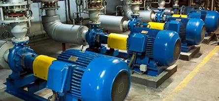
At Tapflo UK we have a large range of Centrifugal Pumps available for a variety of industrial and hygienic applications. Included within our range are our own Tapflo manufactured Centrifugal Pumps and those of our trusted partners so it’s fair to say we know a thing or two about achieving maximum efficiency for your pump and any of our pump technologies. Keep reading to find out more.
Centrifugal Pump Performance Curves

Even though a Centrifugal Pump performance curve displays a wide envelope of capacity that the pump can work within, this does not mean that the pump should be operated at all points on its curve on a consistent or permanent basis. A simple comparison can be made to a car; even though a car can potentially reach speeds of up to 120 mph, for example, you wouldn’t want to consistently run the car at this speed as it would cause increased wear and tear on the engine and result in hefty repair costs, as well as speeding tickets!
It is generally recommended to maintain a moderate and consistent speed whilst maintaining low rpm to get the best efficiency from the engine and reduce wear and tear, this is the same for a Centrifugal Pump. All Centrifugal Pumps have a point in the curve whereby they operate at their highest efficiency, the Best Efficiency Point (BEP). The efficiency curve within a performance chart is usually a half-crescent shape with the percentage of efficiency indicated on the left axis and capacity running along the bottom.
The BEP for a Centrifugal Pump is found at the highest point on this curve. You can determine whether a pump is suitable for your intended application by drawing a line through this point from the capacity line all the way through each of the curves until it intersects with the capacity/headline on the top curve (as shown). If this matches your requirements, the pump is suitable for the intended application. In the example above, the BEP for this specific pump is approx. 14.5 m3/hr at 20 m.
By drawing lines from each of the BEPs on the curves in the chart to intersect with the left-hand axis’, you can also determine the percentage of efficiency of the pump at duty point as well as the absorbed power from the motor, which can then tell you what installed motor power is required. In the example above, the efficiency at BEP is approx. 66% (peak efficiency) and the absorbed power is approx. 1.3 kW.
This would then indicate that the required installed motor power size would need to be at least 1.5 kW. However, it is common practice for mass-produced pumps to be installed with motors which “cover the end of curve”, in this instance 2.2 kW. This is done to cover any unforeseen external factors which may lead to higher power absorption, such as an increase in the fluids specific gravity/viscosity or fluctuations in discharge head.
For example, if the discharge head was originally over-estimated (commonplace) by a matter of 5m and the actual discharge head was 15m instead of the stated 20m, then the absorbed power would then increase to approx. 1.85 kW. This would render the 1.5 kW motor redundant, and the pump would not function without the use of a regulation valve on the discharge of the pump to artificially create the “missing” 5m head. This is done by partially closing the valve to create a restriction in the flow path that produces an extra 0.5 Bar (5m) pressure for the pump to overcome.
Operating a Centrifugal Pump too far on either side of its BEP can be problematic and cause a number of problems for the pump and user. Below is an exaggerated pump curve demonstrating the most common problems. Operating a pump too far to the left or right of the BEP point can result in reduced impeller life, low bearing and seal life, and in extreme cases, cavitation. Each Centrifugal Pump has what is called a ‘Minimum Continuous Safe Flow’, which is the minimum flow that the pump can produce without causing any of the aforementioned problems. This is typically 40% of its BEP. In the example below, it would be 8.7m3/hr.

Ensure your Centrifugal Pump is Operating Efficiently
Cavitation

Simply defined, cavitation is the formation of bubbles or cavities in a liquid, developed in areas of relatively low pressure around an impeller. The imploding or collapsing of these bubbles trigger intense shock waves inside the pump, causing significant damage to the impeller and/or the pump housing. It is typically identified if the pump sounds like it is pumping a bag of marbles or bolts.
If left untreated, pump cavitation can cause:
- Failure of the pump housing
- Destruction of impeller
- Excessive vibration – leading to premature seal and bearing failure
- Higher than the necessary power consumption
- Decreased flow and/or pressure

